


Range Burner Won't Heat or Won't Turn Off? – Fix Surface Element Control Fast
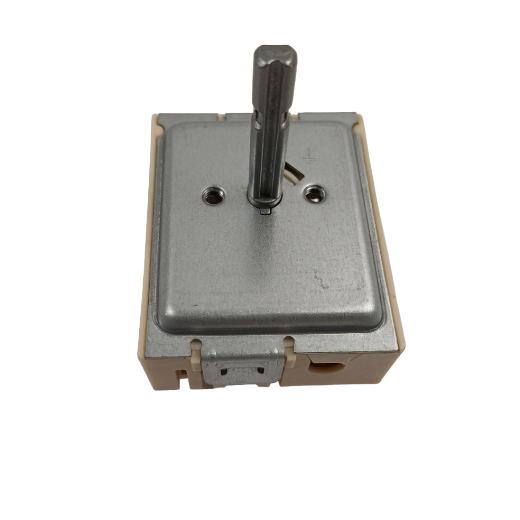
A burner that won't respond, won't shut off, or only heats on one setting is a safety hazard and a repair that can't wait. In most Samsung electric ranges, this is caused by a failed dual surface element control switch. When it fails, one or both burners lose precise heat regulation — they may stay on at full power, refuse to heat at all, or cycle erratically. ⚡ High-failure component in Samsung NE-series ranges. Part DG44-01006B is the genuine OEM replacement that restores full, precise burner control with an exact factory fit.
❓ Is This the Right Part?
This is the correct fix if ALL of the following are true:
- ✔ Range powers on and other functions work normally
- ✔ Oven heating is unaffected — only surface burners are the problem
- ✔ Power supply and breaker confirmed OK
- ✔ Control knob is present and turns freely (not physically broken)
- ✔ ONLY problem is one or both surface burners won't heat, won't turn off, or won't regulate temperature
🔧 Common Symptoms
- Surface burner element won't heat up — most common complaint
- Burner stays on and won't turn off
- Burner only heats on one setting — no temperature control
- Sparking or arcing at the control knob area
- Burner heats inconsistently or cycles on/off unexpectedly
- Control knob feels loose, has no resistance, or spins freely
✔ If these symptoms match, this is the most likely failed component in the system.
✔ In most cases, replacing this control switch restores normal burner operation immediately.
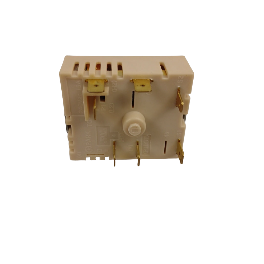
📦 Part Details
- Part Number: DG44-01006B
- Type: Dual Surface Element Control Switch / Infinite Switch / Dual Energy Regulator
- Replaces: PER001-1, PER001-12D, PER001-12 D, PER00112 D, AP5623310, PS4242566, EAP4242566, 180515V, 201210V, 201210 V, 2068783, 2068784 — no modification required
- Production Number: PER001-12 D (printed on part)
- Brands: Samsung
- Model Fit Count: 96 verified models
⚙️ Installation Notes
Skill Level: MODERATE — 30–45 minutes. Disconnect power at the breaker before beginning — this is a high-voltage component. Remove the control panel fascia, photograph all wire connections before disconnecting the old switch, then transfer the control knob and reconnect wires exactly as photographed. Restore power and test all burner heat settings before reassembling the panel.
💡 Pro Tip
Set your multimeter to continuity or resistance mode and test across the switch terminals with the knob at each heat setting. An open circuit at any position confirms a failed switch. This takes 5 minutes and eliminates any doubt before you spend on the part.

NE58F9500SS/AA, NE58F9710WS/AA, NE58K9430SS/AA, NE58K9500SG/AA, NE58K9850WG/AA, NE58K9850WG/AC, NE58K9850WS/AA, NE58K9850WS/AC, NE58R9311SS/AA, NE58R9311SS/AC, NE58R9430SG/AC, NE58R9431SG/AA, NE58R9431SS/AA, NE58R9431ST/AA, NE59J7650WS/AA, NE59J7750WS/AA, NE59J7750WS/AC, NE59J7850WG/AA, NE59J7850WG/AC, NE59J7850WS/AA, NE59J7850WS/AC, NE59K3310SB/AA, NE59K3310SS/AA, NE59K3310SW/AA, NE59K3321SS/AC, NE59M4310SB/AA, NE59M4310SS/AA, NE59M4310SW/AA, NE59M4320SB/AA, NE59M4320SG/AA, NE59M4320SS/AA, NE59M4320SW/AA, NE59M4320SW/AC, NE59M6850SG/AA, NE59M6850SS/AA, NE59R4321SG/AA, NE59R4321SS/AA, NE59R4321SS/AC, NE59T4311SG/AA, NE59T4311SS/AA, NE59T4321SW/AA, NE59T7511SG/AA, NE59T7511SS/AA
✓ Model-Specific Repair Pages
✅Compatibility & Cross Reference
Not sure about your model number? Call 1-877-899-7278 and we’ll help you confirm. All brand names are the property of their respective owners and are used for compatibility reference only.
Buy Online Pick Up In-Store
Kitchener, Ontario N2E 1W8


- Choosing a selection results in a full page refresh.


