


GE Laundry Centre Washer Won’t Start, Shows Error Codes, or Has Unresponsive Controls? Main Control Board WW01F01893 – Fix Control Failure Fast
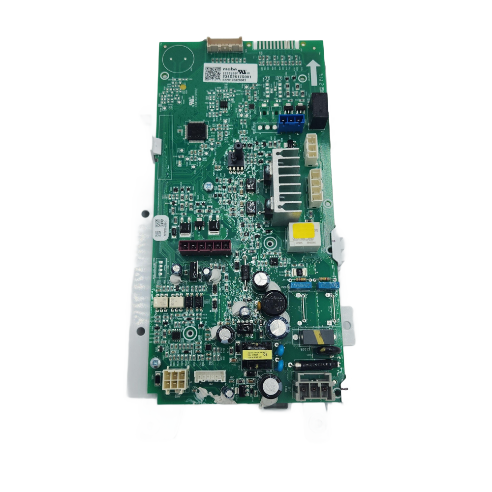
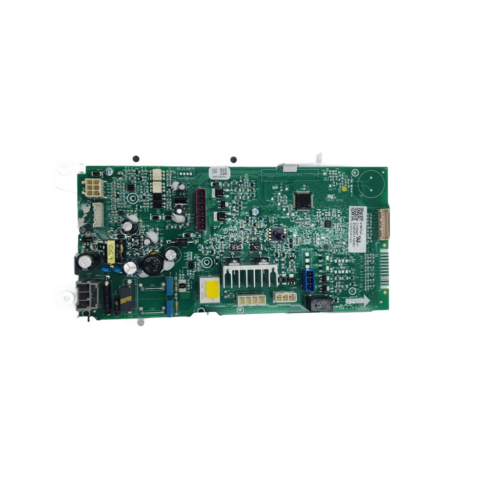
If your GE stacked laundry centre washer won’t start, displays persistent error codes, or has completely unresponsive controls, the main control board is the most likely cause. In most GE GUD, GUV, and XUD series laundry centres, the main control board manages every washer function — cycle selection, water fill, agitation, spin, and diagnostics. When it fails from power surge damage, relay burnout, or component fatigue, the washer loses some or all functions and cannot complete a cycle. ⚡ Common failure point in GE-built stacked laundry centres across the GUD24, GUD27, GUD37, GUV27, and XUD27 families. Part WW01F01893 is the genuine OEM Canadian replacement control board assembly that restores full washer function in a single swap — PCB comes pre-mounted to its support bracket with factory firmware, no programming required.
❓ Is This the Right Part?
This is the correct fix if ALL of the following are true:
- ✔ Power supply to the laundry centre is confirmed good — outlet tested, breaker not tripped
- ✔ Wiring harness connectors have been inspected and confirmed free of corrosion or burned pins
- ✔ Lid lock or door latch assembly has been confirmed working (a failed latch mimics board failure)
- ✔ Inlet fuse or thermal fuse on the board has been checked — a blown fuse is a $5 fix often mistaken for board failure
- ✔ ONLY problem is washer won’t start, stops mid-cycle, shows persistent error codes, or controls are unresponsive
Not sure? Send us your model number — we’ll confirm before you order.
🔧 Common Symptoms
- Washer won’t start — completely unresponsive when Start is pressed
- Controls unresponsive or erratic — buttons don’t register or trigger wrong functions
- Persistent error codes that won’t clear after a power reset
- Washer stops mid-cycle unexpectedly with no error code
- Incorrect cycle behavior — wrong water fill level, agitation pattern, or spin speed
- Washer runs continuously without completing or advancing through a cycle
- Visible burn marks, scorched components, or failed relays on the PCB
✔ If these symptoms match, this is the most likely failed component in the system.
✔ In most cases, replacing this control board restores full washer operation immediately.
📦 Part Details
- Part Number: WW01F01893 (Canadian OEM service number)
- Type: Laundry Centre Washer Main Control Board & Support Assembly (PCB pre-mounted to bracket)
- U.S. Regional Equivalent: WH16X27251
- Production/Engineering Numbers: 234D2621G001, 234D2617G001, 254C1391P001
- Brands: GE Appliances / Mabe
- Firmware: Factory-programmed — no programming required after installation
While the control board is out, inspect all wiring harness connectors for corrosion or burned pins — a damaged connector causes identical symptoms to a failed board and will cause the same failure on the new board if not repaired. Also check the inlet fuse or thermal fuse on the board itself before ordering — a blown fuse is a $5 fix frequently mistaken for board failure.
⚙️ Installation Notes
Skill Level: Intermediate — 30–45 minutes. Disconnect power at the outlet or breaker before beginning. ⚠️ ESD precaution required: ground yourself before handling the PCB — static discharge can permanently damage the board. Photograph all wiring harness connections before disconnecting — multiple connectors must be reinstalled in the correct positions. Access the control board by removing the washer’s control console or rear panel depending on your model. Install the new assembly in the same orientation, reconnect all harnesses, restore power, and run a diagnostic cycle to confirm full functionality before reassembling panels.
💡 Pro Tip
A failed wiring harness and a failed control board produce identical symptoms — no start, error codes, and unresponsive controls. Before installing the new board, inspect all harness connectors for corrosion, burned pins, or loose connections. A single damaged connector can prevent the board from functioning and will cause the same failure on the new board if not repaired. If the board has visible burn marks or a failed relay, the board is confirmed faulty. Always use ESD precautions when handling the new PCB — static discharge is the most common cause of DOA control board failures on installation.

CLME71214BAT00, GUD24ESMM0WW, GUD24ESSM0WW, GUD24ESSM1WW, GUD24GSSM0WW, GUD24GSSM1WW, GUD27EESN0WW, GUD27ESMM0WW, GUD27ESMM1WW, GUD27ESPM0DG, GUD27ESPM1DG, GUD27ESSM0WW, GUD27ESSM1WW, GUD27GSPM0DG, GUD27GSPM1DG, GUD27GSSM0WW, GUD27GSSM1WW, GUD27GSSM2WW, GUD37ESMM0DG, GUD37ESMM1DG, GUV27ESMW0WW, GUV27ESSM0WW, GUV27ESSM1WW, XUD27ESSM0WW, XUD27ESSM1WW, XUD27GSSM0WW, XUD27GSSM1WW
✅Compatibility & Cross Reference
Not sure about your model number? Call 1-877-899-7278 and we’ll help you confirm. All brand names are the property of their respective owners and are used for compatibility reference only.
Buy Online Pick Up In-Store
Kitchener, Ontario N2E 1W8


- Choosing a selection results in a full page refresh.


