WG02F13536 Oven Induction Control Assembly

Sale price
$749.99
Regular price
$1,576.75
You save
$826.76 (52%)

XPart Number: 9665359773985   |   GTIN: 100094970260

Frequently Bought Together

Shipper / Seller: XPart Supply Ltd.

Professional: 120-180 minutes
DIY: 180-240 minutes
Difficulty Level: Difficult repair (requires extensive disconnection/reconnection of multiple connectors, risk of electrical damage if misconnected)

  • Cooktop not heating (no heat output from any element)
  • Induction elements not responding to control inputs
  • Cooktop displays error codes
  • Uneven or inconsistent heating
  • Cooktop shuts off unexpectedly during cooking
  • Cooling fan runs continuously (won't turn off)
  • Cooling fan doesn't run when elements are active
  • Display panel blank or shows garbled characters
  • Control buttons not responding
  • Elements won't turn on
  • Elements stuck at one power level (won't adjust)
  • Cooktop makes unusual buzzing or clicking noises
  • Intermittent operation (works sometimes, not others)
  • Visible damage to control assembly (burned components, corrosion)
  • Cooktop won't detect cookware (no cookware error)

WB27X33085, WB27X33086, WB27X24265, WG02A02735, WG02F10941, WG02F11570, WG02F13537, PS12068871, AP6263233, 5303051516, 5303051517, WB27X27843

Fits Models: (Ctrl+F and Enter Your Model Number)

GE: PHP9036SJSS, PHP9036DJBB, PHP9036DJWW, PHP9036SLSS, PHP9036DLBB, PHP9036DLWW, PHS930SLSS, PHS930YPFS, PHS930BLTS, PHS930SLTS

GE (continued): PHS930YPFS, PHS930BLTS, PHS930SLTS, PHP960DMBB, PHP960DMWW, PHP960SMSS, PHP960DPBB, PHP960DPWW, PHP960SPSS, PHS920SFSS

GE (continued): PHS920YPFS, PHS920BLTS, PHS920SLTS, PHP9030SJSS, PHP9030DJBB, PHP9030DJWW, PHP9030SLSS, PHP9030DLBB, PHP9030DLWW, PHP9030DPBB

GE (continued): PHP9030DPWW, PHP9030SPSS, PHP9030SLSS, PHP9024SJSS, PHP9024DJBB, PHP9024DJWW, PHP9024SLSS, PHP9024DLBB, PHP9024DLWW, PHP9024DPBB

Hotpoint: RAS200DMWW, RAS200DMBB, RAS200DMCC, RAS300DMWW, RAS300DMBB, RAS300DMCC, RAS400DMWW, RAS400DMBB, RAS400DMCC, RAS500DMWW

Hotpoint (continued): RAS500DMBB, RAS500DMCC, RAS600DMWW, RAS600DMBB, RAS600DMCC, RAS700DMWW, RAS700DMBB, RAS700DMCC, RAS800DMWW, RAS800DMBB

Kenmore: 79572022010, 79572022011, 79572022012, 79572022013, 79572022014, 79572022015, 79572022016, 79572022017, 79572022018, 79572022019

Haier: HCR2250IDS, HCR2250IDW, HCR2250ICS, HCR2250ICW, HCR3250IDS, HCR3250IDW, HCR3250ICS, HCR3250ICW, QAS740IMSS, QAS740INSS

Note: This is a partial list. This induction control assembly is used in many GE-manufactured induction ranges and wall ovens built between 2015-2024. Verify your specific model number for compatibility before ordering. Induction control assemblies are model-specific—using an incompatible assembly will cause malfunction.

Required Tools:

  • Phillips screwdriver
  • Flathead screwdriver
  • 1/4" or 5/16" nut driver
  • Torx screwdriver set (T10, T15, T20)
  • Needle-nose pliers
  • Work gloves
  • Flashlight
  • Towel or blanket (to protect cooktop surface)
  • Camera or smartphone (for reference photos)
  • Anti-static wrist strap (recommended)
  • Multimeter (for electrical testing)

Step-by-Step Installation:

  1. Disconnect Power: Turn off the circuit breaker that supplies power to the range. Verify power is off by attempting to turn on the cooktop (nothing should happen). Never work on the range with power connected. Wait 10 minutes for capacitors to discharge before proceeding.
  2. Move Range (if freestanding): If you have a freestanding range, pull it away from the wall to provide access to the rear and underside. You'll need at least 3 feet of clearance.
  3. Remove Cooktop Surface (if necessary): Depending on your model, you may need to remove the cooktop glass surface to access the control assembly:Remove screws securing the cooktop frame (typically 4-8 screws around the perimeter)Carefully lift the cooktop glass surface and set it aside on a padded surfaceHandle the glass carefully to avoid breakage
  4. Access Control Assembly from Below: For most models, the induction control assembly is accessible from below the cooktop:If you have a slide-in or drop-in range, remove the lower access panel or drawerIf you have a freestanding range, tip the range back slightly or access from the rear
  5. Locate Control Assembly: Look at the underside of the cooktop. You'll see the induction control assembly—a large electronic module with multiple wire harness connectors, cooling fins or heat sinks, and mounting brackets.
  6. Take Reference Photos (Critical): Before disconnecting anything, take 30-40 clear, close-up photos of ALL wire harness connections to the control assembly. Photograph each connector from multiple angles showing:Wire colors and connector positionsConnector orientation and locking mechanismsRelative position of each connector on the assemblyAny labels or markings on connectorsCooling fan connectionsPower input connections Label each connector with masking tape and marker if needed (e.g., "Element 1," "Element 2," "Display," "Power," "Fan," etc.). This is absolutely critical for correct reinstallation.
  7. Document Connector Positions: Create a detailed diagram or written list showing which connector connects to which port on the assembly. Include wire colors if visible. This documentation prevents misconnection during reinstallation.
  8. Disconnect Cooling Fan (if present): If the control assembly has a cooling fan, disconnect the fan wire connector. Press the release tab and pull the connector straight off.
  9. Disconnect Main Power Connector: Locate the main power input connector (typically the largest connector). Press the release tab and pull straight off.
  10. Disconnect Wire Harnesses: The control assembly will have multiple wire harness connectors (typically 10-20 connectors depending on model). Carefully disconnect each connector one at a time:Press the release tab or locking mechanism on each connectorPull the connector straight off—do not pull on wires, only on the connector housingKeep track of which connector goes where using your photos and labelsPlace each connector in a small container or bag labeled with its function
  11. Remove Mounting Hardware: The control assembly is secured with mounting screws or clips (typically 4-8 fasteners). Remove all mounting hardware. Keep these fasteners—you'll need them for reinstallation.
  12. Remove Old Control Assembly: Once all connections and mounting hardware are removed, carefully lift the old control assembly away from the mounting location. Handle gently to avoid damaging other components or sharp edges.
  13. Inspect Old Control Assembly: Examine the old assembly for visible damage: burned components, melted plastic, corrosion, moisture damage, blown fuses, or discolored areas. This helps confirm the diagnosis and identify the cause of failure. Check for signs of power surge damage or thermal stress.
  14. Clean Mounting Area: Wipe down the mounting surface where the control assembly was located. Remove any dust, debris, or corrosion. A clean mounting surface ensures proper assembly installation and heat dissipation.
  15. Compare Old and New Assemblies: Remove the new control assembly from its packaging (use anti-static precautions—touch a grounded metal surface before handling). Compare the new assembly to the old assembly:Verify connector locations match exactlyCheck that mounting hole positions are identicalConfirm part numbers match or are compatibleEnsure the assembly is the correct replacement for your range model
  16. Position New Control Assembly: Carefully position the new control assembly into the mounting location. Align mounting holes with the mounting points on the cooktop frame or underside.
  17. Install Mounting Hardware: Secure the control assembly with mounting screws or clips. Tighten screws firmly but do not overtighten—excessive force can crack the plastic housing or damage the assembly.
  18. Reconnect Wire Harnesses (Critical Step): Using your reference photos and labels, reconnect all wire harness connectors to the new control assembly. This is the most critical step:Match each connector to its correct port on the assemblyEnsure connectors are oriented correctly (they typically only fit one way)Push each connector straight on until you hear or feel a clickVerify the locking tab engages on each connectorGently tug each connector to ensure it's fully seated and won't pull offDouble-check every connection against your photos before proceeding
  19. Reconnect Main Power Connector: Plug the main power input connector back onto the control assembly. Ensure the connection is secure and fully seated.
  20. Reconnect Cooling Fan (if present): Plug the cooling fan wire connector back onto the control assembly. Ensure the connection is secure.
  21. Verify All Connections: Before closing panels, carefully verify that:All wire connectors are attached to the correct portsNo connectors are loose or partially connectedNo wires are pinched, damaged, or touching sharp edgesAll locking tabs are engagedThe assembly is securely mountedNo wires are trapped between the assembly and mounting surface
  22. Reinstall Cooktop Surface (if removed): If you removed the cooktop glass surface, carefully position it back onto the frame and secure with all mounting screws. Ensure the glass is properly seated and aligned.
  23. Reinstall Access Panels: Replace any lower access panels or drawers you removed. Secure with all mounting screws.
  24. Move Range Back (if moved): If you moved the range, push it back into position, leaving a small gap from the wall for ventilation.
  25. Restore Power: Turn on the circuit breaker that supplies power to the range.
  26. Initial Power-Up: When power is restored, the control assembly will initialize. You may hear beeps, see the display light up, or hear relays clicking. This is normal. Some models require 5-10 minutes for the control assembly to complete initialization.
  27. Test Display Panel: Verify the control panel lights up and responds to button presses:Press buttons and verify the display changesCheck that all display segments work (numbers, letters, symbols)Verify the display shows the correct information
  28. Test Induction Element Operation: Place an induction-compatible pot or pan on one of the heating elements. Set the element to MEDIUM power and press START:The element should activate within 5-10 secondsYou should hear the cooling fan startThe pot/pan should begin heatingThe display should show the element is active
  29. Verify Heating Performance: Allow the element to heat for 2-3 minutes. The pot/pan should heat rapidly and evenly. Induction heating is very fast—water should boil in 3-5 minutes.
  30. Test All Heating Elements: Test each induction heating element individually to verify all are working:Place a pot/pan on each elementSet each element to MEDIUM powerVerify each element heats properlyCheck that power levels adjust correctly (LOW, MEDIUM, HIGH)
  31. Test Power Level Control: For each element, test all power levels:LOW: Element should heat gentlyMEDIUM: Element should heat moderatelyHIGH: Element should heat rapidlyBOOST (if equipped): Element should heat at maximum power The element should respond to power level changes within 5-10 seconds.
  32. Verify Cooling Fan Operation: During heating, verify the cooling fan runs continuously. The fan should be audible but not excessively loud. The fan should continue running for several minutes after the elements are turned off to cool the control assembly.
  33. Test Safety Features: Test the cooktop's safety features:Remove the pot/pan from an active element—the element should shut off within 30-60 seconds (no cookware detection)Place a non-induction pot/pan on an element—the element should display an error or not activate (incompatible cookware detection)Test the child lock feature (if equipped)
  34. Check for Error Codes: Monitor the display panel for any error codes. If error codes appear, consult your range's service manual to diagnose. Some error codes indicate additional component failures or incorrect assembly installation.
  35. Monitor for 30 Minutes: Allow the cooktop to heat and operate for 30 minutes. Monitor for:Stable heating performanceNormal cooling fan operationNo error codes or unusual displaysNo unusual noises (buzzing, clicking, or arcing)Normal operation of all features
  36. Full Cooking Test: Run a complete cooking test:Boil water on multiple elements simultaneouslyTest high-power and low-power settingsVerify temperature control is accurate and responsiveCook a test meal to verify proper heating and performance
  37. Monitor for 24 Hours: Allow the range to operate for 24 hours and monitor for any issues: unusual noises, error codes, or operational problems.

Diagnose before replacing—induction control assemblies are very expensive and often misdiagnosed. The induction control assembly is one of the most expensive range components ($600-900), and it's frequently replaced unnecessarily. Before ordering a control assembly, systematically test other components: induction heating elements (test for proper resistance and continuity), cooling fan (test for operation), temperature sensors (test for proper resistance), and power supply (verify 240V at the control assembly input). An estimated 40% of control assembly replacements are unnecessary—the actual problem is a failed heating element ($200-350), cooling fan ($60-100), or power supply issue ($150-250). A $200 heating element can cause the same symptoms as a $900 control assembly.

Take extensive photos and label everything—induction control assemblies have the highest reinstallation error rate. With 15-20 wire connectors that look similar, it's extremely easy to connect wires to the wrong ports, causing immediate assembly failure, component damage, or electrical shorts. Take 40-50 photos from

multiple angles before disconnecting anything. Label every connector with tape and marker. Create a detailed written diagram showing connector positions and wire colors. Compare your photos constantly during reinstallation. One misconnected wire can destroy your new $900 assembly instantly. Professional technicians spend 30-45 minutes documenting connections before starting removal—this is not optional.

Check for power surges and electrical issues before installing the new assembly. If your control assembly failed due to a power surge or voltage spike, installing a new assembly without addressing the electrical issue will destroy the new assembly immediately. Test the outlet voltage (should be 240V AC ±10%). Check for evidence of power surges: burned components, melted plastic, corrosion, or discolored areas on the old assembly. If surge damage is evident, install a whole-house surge protector ($300-500) before installing the new assembly. Many manufacturers void warranties if surge damage is evident.

Verify the cooling fan is working before blaming the control assembly. The induction control assembly generates significant heat during operation and relies on a cooling fan to prevent overheating. If the cooling fan fails, the control assembly overheats and shuts down or fails completely. Before ordering a new control assembly, test the cooling fan for proper operation. If the fan doesn't run or runs slowly, replace the fan ($60-100) before replacing the assembly. Installing a new assembly with a failed cooling fan causes the new assembly to overheat and fail within weeks.

Test individual heating elements before replacing the entire control assembly. If only one or two heating elements are not working while others function normally, the problem is likely a failed heating element ($200-350), not the control assembly. Test each heating element for proper resistance and continuity using a multimeter. If an element reads infinite ohms (OL) or zero ohms, it's failed and should be replaced. Replacing a $200-350 failed element is much cheaper than replacing a $900 control assembly. Only replace the control assembly if multiple elements fail or if power delivery to all elements is affected.

Induction control assemblies are non-returnable and non-refundable. Almost all appliance parts suppliers have strict no-return policies on control assemblies because they're easily damaged by incorrect installation, static electricity, or misdiagnosis. Once you install a control assembly and apply power, it cannot be returned even if it doesn't work. Verify your diagnosis thoroughly before ordering. Use a multimeter to test components. Consult the range service manual for error code meanings. Only order the control assembly after you've eliminated all other possibilities.

WG02F13536 vs WG02F13537—verify which version you need. These two part numbers are very similar and often confused. WG02F13536 is for specific GE induction range models, while WG02F13537 is a kit version that includes additional components. Verify your exact model number and compare the old assembly part number before ordering. Installing the wrong version causes immediate malfunction or incompatibility. Check your range's model/serial plate and cross-reference with the manufacturer's parts diagram.


Whirlpool refrigerator replacement parts, Frigidaire refrigerator replacement parts, GE refrigerator replacement parts, Kenmore refrigerator replacement parts, KitchenAid refrigerator replacement parts, LG refrigerator replacement parts, Maytag refrigerator replacement parts, Whirlpool refrigerator drawers and glides replacement, Whirlpool dishwasher replacement parts, GE dishwasher replacement parts, KitchenAid dishwasher replacement parts, Maytag dishwasher replacement parts, Frigidaire dishwasher replacement parts, Kenmore dishwasher replacement parts, Whirlpool washer replacement parts, GE washer replacement parts, Maytag washer replacement parts, Kenmore washer replacement parts, LG washer replacement parts, Whirlpool dryer replacement parts, GE dryer replacement parts, Maytag dryer replacement parts, Kenmore dryer replacement parts, LG dryer replacement parts, Whirlpool range replacement parts, GE range replacement parts, Whirlpool stove replacement parts, GE stove replacement parts, GE oven replacement parts, GE microwave replacement parts, buy Whirlpool refrigerator parts online, buy GE dishwasher parts online, replacement Kenmore washer parts for sale, buy Maytag dryer parts, LG washer replacement parts online, KitchenAid refrigerator parts for sale, Whirlpool stove and range replacement parts

WG02F13536 Oven Induction Control Assembly

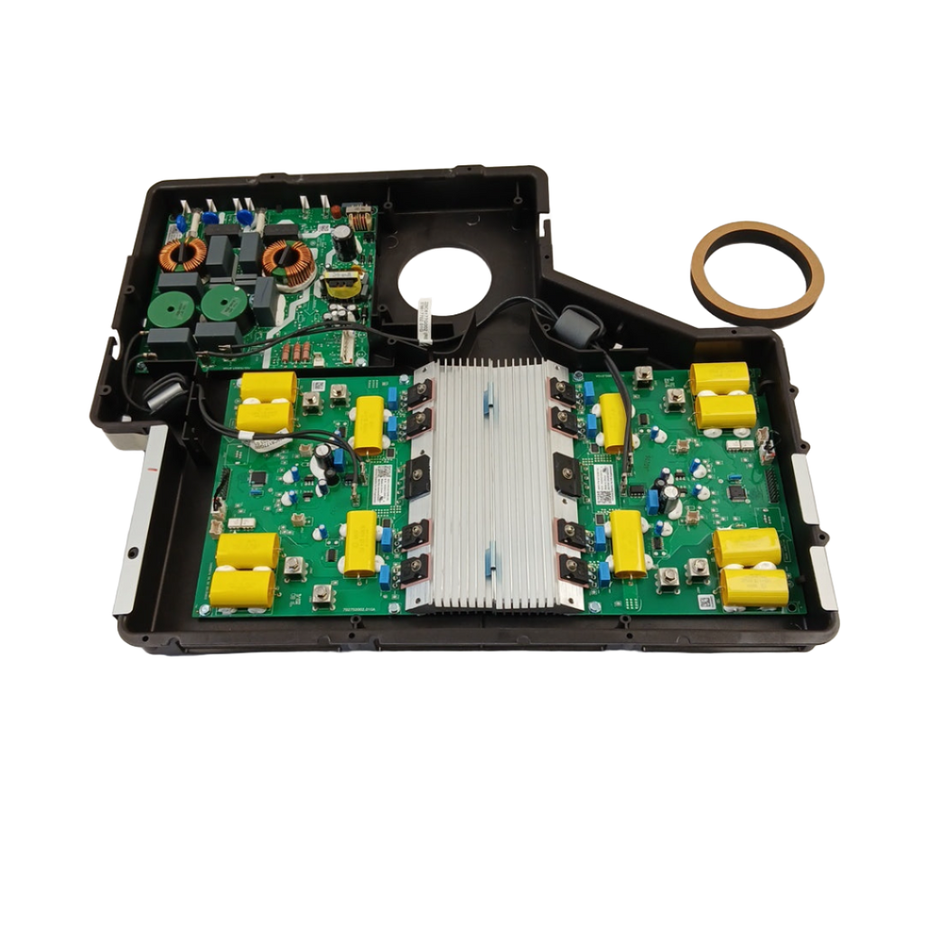
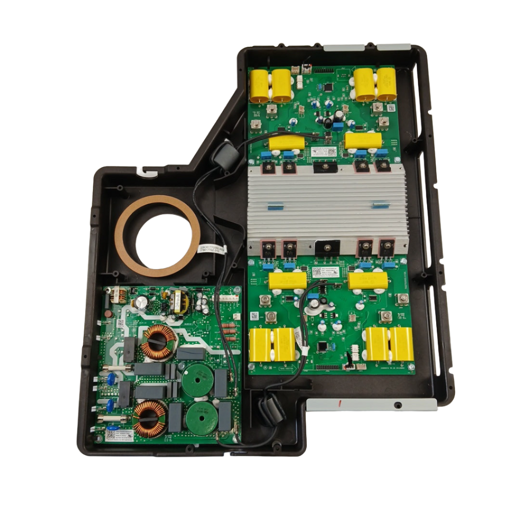
Genuine OEM induction oven control assembly for GE induction ranges and wall ovens. This critical component is the electronic control system that regulates power delivery to the induction heating elements, manages temperature control, monitors safety systems, and interfaces with the user control panel. The assembly includes the power control board, induction element driver circuits, temperature sensors, safety relays, cooling fan control, and connector terminals. Unlike traditional electric or gas ovens, induction ovens use electromagnetic fields to directly heat cookware, requiring sophisticated electronic control systems to manage power delivery and ensure safe operation. When this component fails, you'll experience the oven not heating, heating elements not responding to control inputs, error codes displayed on the control panel, uneven or inconsistent heating, the oven shutting off unexpectedly, cooling fan running continuously, or the control panel being unresponsive. Induction control assemblies fail due to power surges, thermal stress from high heat exposure, component wear, electrical shorts, manufacturing defects, or water/moisture exposure. The control assembly is typically located beneath the cooktop surface or in a separate control box mounted to the oven frame. This part is equivalent to WB27X33085.

Key Features and Design

  • Advanced Technology: Features an OEM PCB with integrated heatsink and high-quality capacitors for optimal performance and heat dissipation, as seen in its sturdy, compact design.
  • Durable Construction: Built with robust materials to withstand daily use, offering long-lasting reliability for high-performance induction cooking.
  • Compatibility: Seamlessly replaces parts like WG02A02734 and WB27X33085, fitting models such as Café™ 30" and 36" smart touch-control induction cooktops, GE Profile 30" units, and Monogram 36" cooktops.

Performance and Benefits

This control assembly delivers precise temperature control to reduce cooking times and minimize energy waste, making it a smart upgrade for enhancing your overall cooking experience. By solving issues like inconsistent heating, it promotes efficient operation and reliable results, backed by XPart Supply Ltd.'s commitment to quality-tested parts for peace of mind in your kitchen.

This induction control assembly (WG02F13536) is a vital component of your oven, ensuring precise temperature control and faster cooking times. With its advanced technology and durable design, this product guarantees high performance and efficient results every time. Upgrade your cooking experience with this top-of-the-line assembly.

Replaces Part Numbers WG02A02734, WB27X33085


Fits Supported Models:

CHP95302M3SS CAFÉ™ 30" SMART TOUCH-CONTROL INDUCTION CCHP95362M3SS CAFÉ™ 36" SMART TOUCH-CONTROL INDUCTION COOKTOP C
PHP9030DJ5BB GE Profile 30" Induction Cooktop Black C ZHU36RSJ4SS Monogram 36" Induction Cooktop Silver C

Past Part Numbers (Superseded)

WB27X33085, WB27X33086, WB27X24265, WG02A02735, WG02F10941, WG02F11570, WG02F13537, PS12068871, AP6263233, 5303051516, 5303051517, WB27X27843

Compatible with the following models

GE: PHP9036SJSS, PHP9036DJBB, PHP9036DJWW, PHP9036SLSS, PHP9036DLBB, PHP9036DLWW, PHS930SLSS, PHS930YPFS, PHS930BLTS, PHS930SLTS

GE (continued): PHS930YPFS, PHS930BLTS, PHS930SLTS, PHP960DMBB, PHP960DMWW, PHP960SMSS, PHP960DPBB, PHP960DPWW, PHP960SPSS, PHS920SFSS

GE (continued): PHS920YPFS, PHS920BLTS, PHS920SLTS, PHP9030SJSS, PHP9030DJBB, PHP9030DJWW, PHP9030SLSS, PHP9030DLBB, PHP9030DLWW, PHP9030DPBB

GE (continued): PHP9030DPWW, PHP9030SPSS, PHP9030SLSS, PHP9024SJSS, PHP9024DJBB, PHP9024DJWW, PHP9024SLSS, PHP9024DLBB, PHP9024DLWW, PHP9024DPBB

Hotpoint: RAS200DMWW, RAS200DMBB, RAS200DMCC, RAS300DMWW, RAS300DMBB, RAS300DMCC, RAS400DMWW, RAS400DMBB, RAS400DMCC, RAS500DMWW

Hotpoint (continued): RAS500DMBB, RAS500DMCC, RAS600DMWW, RAS600DMBB, RAS600DMCC, RAS700DMWW, RAS700DMBB, RAS700DMCC, RAS800DMWW, RAS800DMBB

Kenmore: 79572022010, 79572022011, 79572022012, 79572022013, 79572022014, 79572022015, 79572022016, 79572022017, 79572022018, 79572022019

Haier: HCR2250IDS, HCR2250IDW, HCR2250ICS, HCR2250ICW, HCR3250IDS, HCR3250IDW, HCR3250ICS, HCR3250ICW, QAS740IMSS, QAS740INSS

Note: This is a partial list. This induction control assembly is used in many GE-manufactured induction ranges and wall ovens built between 2015-2024. Verify your specific model number for compatibility before ordering. Induction control assemblies are model-specific—using an incompatible assembly will cause malfunction.

BUILT TOUGH · PARTS THAT LAST · GUARANTEED

Trusted Family Business

30 years of Excellence in Appliance Parts

Whether you need a refrigerator water filter, a replacement burner for your stove, or a dryer belt, XPart Supply has you covered. We carry a wide selection of appliance parts in Kitchener-Waterloo for all major brands, including washers, dryers, refrigerators, dishwashers, ovens, and more.

We also offer used appliances and scratch-and-dent appliances in Kitchener-Waterloo, providing affordable, reliable options for customers looking to save money without sacrificing performance. Every appliance is inspected and tested for quality.

For over 30 years, our family-owned business has proudly served the community with quality appliance parts and exceptional service. What started as a small local shop has grown into a trusted name — but we’ve never forgotten our roots. Every customer receives the personal attention and care that only a family-owned business can provide.

When you need appliance parts, used appliances, or scratch-and-dent appliances in Kitchener-Waterloo, trust XPart Supply — Built Tough. Parts That Last.

Years of Experience

Our knowledge has been built over the past 30 years in the business, ensuring expert advice for every appliance need.

Personal Service Guarantee

We treat every customer like family, providing personalized solutions and standing behind our products.

Built on Trust

Our reputation has been built one satisfied customer at a time, creating lasting relationships in our community.

Contact Us Customer Service

Hard to find parts? We've got them or we'll find them!

Call now for expert appliance parts assistance

Business Hours: Mon–Fri 9 AM–5 PM • Sat 9 AM–1 PM

Buy Online Pick Up In-Store

Address
101 Trillium Dr
Kitchener, Ontario N2R 1J8
Phone
Hours
Mon–Fri 9 AM–5 PM • Sat 9 AM–1 PM
Get Directions