

Equivalent PartsCross-reference listings may have additional stockCheck Stock →
BURNER NOT HEATING AT ALL (NO HEAT AT ANY SETTING)
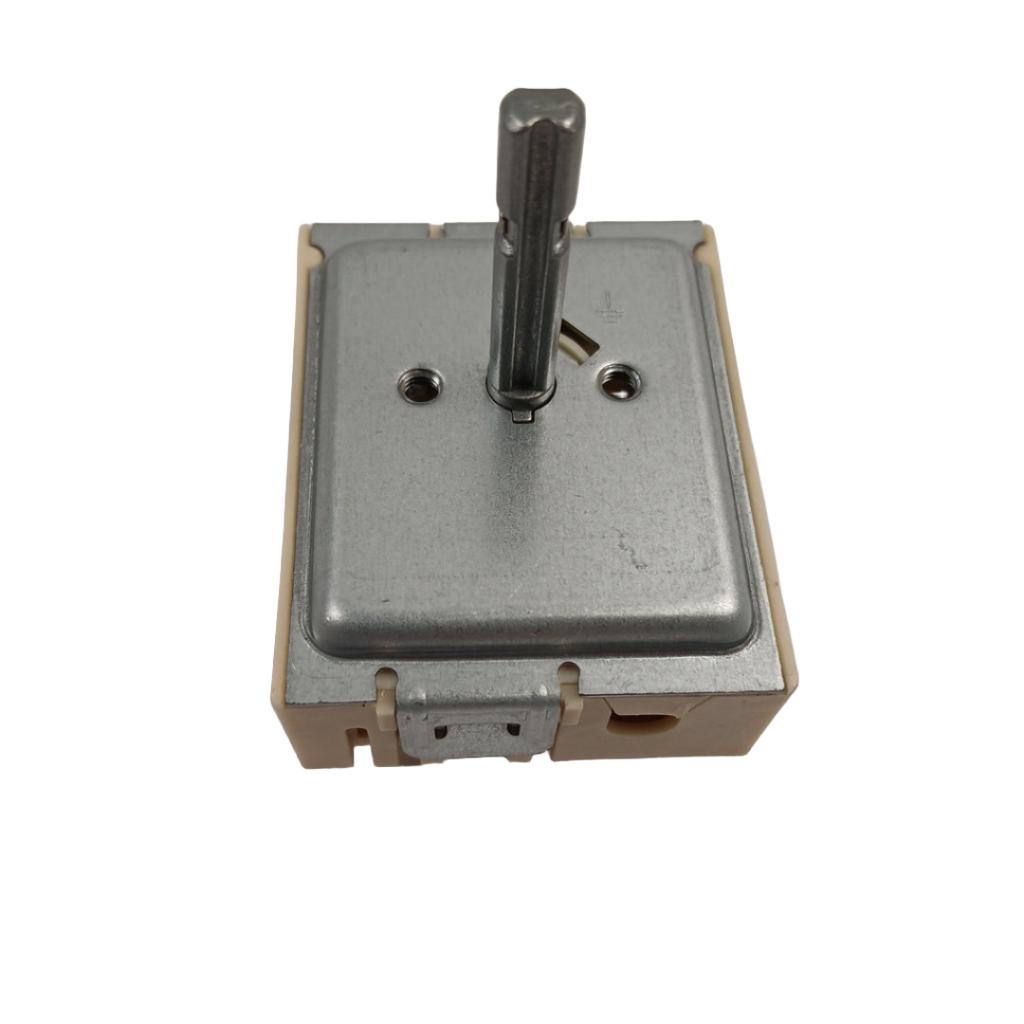
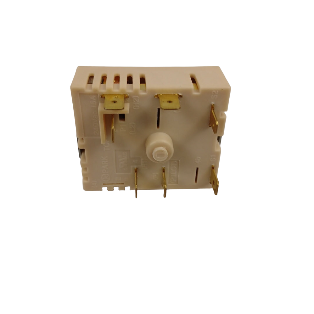
Samsung Range Dual Surface Element Control Switch DG44-01006B, Fixes Burner not heating at all (no heat at any setting)
Genuine Samsung dual surface-element control switch that turns a dual radiant surface element on and off and regulates its heat output.
Part DG44-01006BSamsung
Guaranteed to Fit — or your money back.
Confirm your full appliance model number before ordering.
Confirm your full appliance model number before ordering.
Is This the Right Part?
Part NumberDG44-01006B
ManufacturerSamsung
Appliance TypeRange
Part TypeDual Surface Element Control Switch
✅ Cross Reference Information
Current Part NumberDG44-01006B
Common Symptoms
- Burner not heating at all (no heat at any setting)
- Burner heating continuously without cycling off (stuck on high)
- Burner heating inconsistently or intermittently
- Burner only working on certain settings (high works but low doesn't)
- Visible arcing or sparking at switch terminals
- Burnt smell coming from control panel area
- Control knob feels loose or doesn't engage properly
- Burner cycles erratically (on/off timing is incorrect)
- Burner overheats excessively
- Dual element function not working (only one element heats)
- Switch makes buzzing or clicking noises
- Control knob is difficult to turn or sticks
Check Before Replacing
- With power disconnected, verify the switch wiring and terminals are secure and match the original arrangement.
- If the burner remains on high, does not heat, or fails to respond to knob adjustments, the switch may be defective; verify the element and wiring before replacing it.
- Confirm the replacement switch matches the appliance model and the original part configuration.
Pro Tip
Always label wire connections before disconnecting them.
Part Details
Part NumberDG44-01006B
Part TypeDual Surface Element Control Switch
ManufacturerSamsung
Appliance TypeRange
Installation Notes
- Turn off the circuit breaker
- to the range at the electrical panel to ensure complete power disconnection.
- Verify power is off
- by attempting to turn on a surface burner. The burner should not heat and the control panel should not respond.
- Allow the range to cool completely
- if it was recently used. The cooktop surface and switches can retain heat for several hours.
- Remove all cookware, grates, and burner caps
- from the cooktop surface.
- Pull the range away from the wall
- to provide adequate working space for accessing the rear panel or control panel.
- Take multiple photos
- of the range control panel and any visible wiring before disassembly. Document the switch location, knob position, and wire connections from multiple angles. This is critical for proper reassembly.
- Remove the control knob
- from the faulty switch by pulling it straight off. Most knobs simply pull off, but some may have a set screw that must be loosened first.
- Determine the control panel access method.
- Some ranges require rear panel removal, while others require lifting the cooktop or removing the front control panel. Consult the service manual for your specific model if uncertain.
- For rear-panel access models:
- Remove the screws around the perimeter of the rear panel (typically 8-12 screws). Carefully pull the rear panel away and set it aside.
- For cooktop-lift access models:
- Remove the screws or clips that secure the cooktop (typically 2-4 screws at the front edge). Carefully lift the cooktop up and prop it open with a support rod or block of wood.
- For front control panel access models:
- Remove the screws that secure the control panel (typically 4-6 screws along the top or sides). Carefully pull the control panel forward to access the switches behind it.
- Locate the faulty surface element switch
- behind the control knob you removed. The switch is typically mounted on a bracket or directly to the control panel.
- Take a photo of the switch wire connections
- before disconnecting anything. The switch typically has 3-5 wire terminals labeled with letters or numbers (e.g., H1, H2, L1, L2, P).
- Label each wire terminal
- with masking tape and a marker to identify its connection point (e.g., "H1 terminal - red wire," "L2 terminal - white wire").
- Carefully disconnect the wire terminals
- from the switch one at a time. The wires are typically connected with push-on spade connectors. Pull connectors straight off—do not twist or bend.
- Verify all wires are disconnected
- before attempting to remove the switch.
- Remove the mounting screws or clips
- that secure the switch to the mounting bracket or control panel (typically 1-2 screws or spring clips).
- Carefully remove the old switch
- from the control panel, noting its orientation and position.
- Inspect the old switch
- for visible damage such as burnt terminals, melted plastic housing, arcing marks, or discoloration. This confirms the diagnosis.
- Inspect all wire terminals
- for corrosion, melted insulation, or damage. Clean corroded terminals with a small wire brush or replace damaged wire connectors before installing the new switch.
- Unpack the new DG44-01006B switch
- from its packaging. Handle carefully to avoid damaging the terminals or internal mechanism.
- Compare the new switch to the old one
- to verify the terminal configuration, mounting hole positions, shaft length, and overall appearance match. Ensure you have the correct replacement part.
- Position the new switch
- in the same location and orientation as the old switch.
- Secure the switch
- with the mounting screws or clips, tightening firmly but not over-tightening (which can crack the switch housing).
- Reconnect each wire terminal
- to the new switch, matching the labels you applied earlier. Ensure each connector is fully seated on the switch terminal.
- Verify the connections are secure
- by gently tugging on each wire. The connectors should not pull loose.
- Double-check terminal positions
- to ensure no wires are reversed or misaligned. Incorrect connections can cause the burner to malfunction or create a fire hazard.
- Verify no wires are pinched or kinked
- between the switch and the control panel or mounting bracket.
- Reinstall the control panel, cooktop, or rear panel
- by reversing the disassembly steps. Secure all screws and clips.
- Reinstall the control knob
- by aligning it with the switch shaft and pushing it firmly onto the shaft. If the knob has a set screw, tighten it securely.
- Push the range back into position
- against the wall.
- Turn the circuit breaker back on
- to restore power.
- Test the repaired burner
- by turning the control knob to a medium setting.
- Verify the burner heats properly
- at the medium setting. The heating element should glow red within 30-60 seconds.
- Test the burner at low, medium, and high settings
- to verify proper heat control at all levels.
- Verify the burner cycles on and off
- at lower settings. At low heat, the burner should cycle on for a few seconds, then off for several seconds to maintain low temperature.
- Verify the burner stays on continuously
- at high settings. At high heat, the burner should glow bright red and remain on continuously.
- Test the dual element function
- (if applicable). Some switches control both inner and outer elements. Verify both elements heat when the switch is set to the appropriate position.
- Listen for unusual noises
- such as buzzing, clicking, or arcing sounds from the switch. The switch should operate silently.
- Check for burnt smells
- coming from the control panel area. There should be no burnt plastic or electrical odors.
- If the burner does not heat
- , turn off the range and verify the switch wire connections are secure and correctly positioned.
- If the burner heats continuously without cycling
- , the switch may be faulty or wired incorrectly. Verify wire connections match your labels and photos.
- If the burner only works on certain settings
- , verify all wire terminals are fully seated and the switch is properly mounted.
- If arcing or sparking occurs
- , turn off the range immediately and verify wire connections are secure and not touching each other or metal surfaces.
- Run a cooking test
- by boiling water or cooking a simple recipe to verify the burner maintains consistent heat throughout the cooking cycle.
- Monitor the burner for 24-48 hours
- of normal use to ensure it operates properly at all heat settings.
- Safety Notes:
- Always turn off the circuit breaker before working on the range. Never operate the range without the control panel or cooktop properly installed. Ensure proper wire connections to prevent electrical shorts or fires. If you're uncomfortable working with electrical components, consult a professional technician. Never touch heating elements while they're hot or energized.
Verified Compatible Models
Fitment reminder: Verified compatibility is maintained by the XPart Model Hub Network. Match the complete appliance model number before ordering.
Buy Online Pick Up In-Store
Address
101 Trillium Dr
Kitchener, Ontario N2E 1W8
Kitchener, Ontario N2E 1W8
Phone
Hours
Mon–Fri 9 AM–5 PM • Sat 9 AM–1 PM